
Power distribution system in a mine
Electricity’s application in the mining industry is a distinct area of both mining engineering and electrical engineering. Mining’s difficult environment, dynamic power loads, cyclic and mobile operation, and stringent safety requirements all place unique demands on the mine power system.
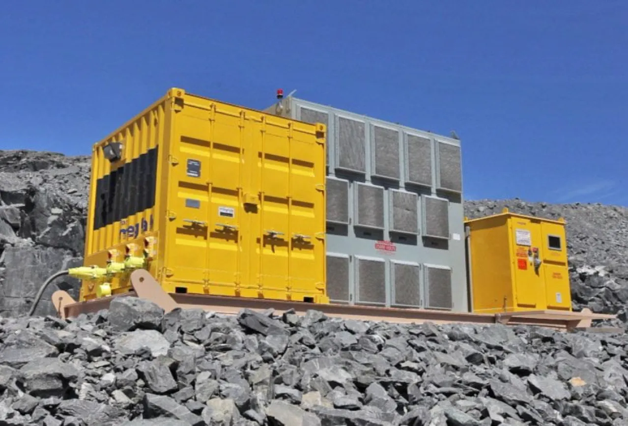
Mine power distribution system grounding (on photo: underground mine substation; credit: ie-corp.com)
A suitable grounding system has always been a difficult problem for the coal mining industry, more complex and difficult than in other industries.
No other industry employs as much portable extensible equipment or has such complex grounding issues. Mine power systems can range from simple installations for small surface mines to complex underground systems where the harsh environment of dust, humidity, and cramped spaces tests the engineer’s ingenuity and creativity to provide reliable service.
The connection to earth or ground, known as the mine grounding system, is an essential component of any mine power distribution system. This is what we will talk about today.
- The reasons for grounding the system
Mine grounding systems are made up of grounded or grounding conductors that run from the ground beds to the equipment. A grounded conductor is a power conductor that is connected to the grounding system; a grounding conductor is distinct from the power conductors and is only used to ground exposed metallic parts of the power system. A ground bed is a complex of conductors placed in the earth to provide a low-resistance connection to the “infinite” earth. It is also known as a ground mesh or grounding electrode, among other names. The grounding system protects personnel and machinery from the hazards associated with improperly operating electrical equipment.
The protection provided can be divided into four functions, which are the primary reasons for grounding the system. - First, potential gradients between conducting materials in a given area must be limited by the grounding system. During a ground fault, for example, a phase conductor contacts a machine frame, and current flows through the equipment; as a result, the potential of the equipment tends to rise above ground potential by an amount equal to the voltage on the conductor. When a person touches a machine frame, the maximum potential to which they are exposed is equal to the voltage drop along the grounding conductors. As a result, the grounding system must provide a low-resistance path for the fault current to return to the source, and the ground conductors must be low resistance in order to carry the maximum expected fault current without causing excessive voltage drop.
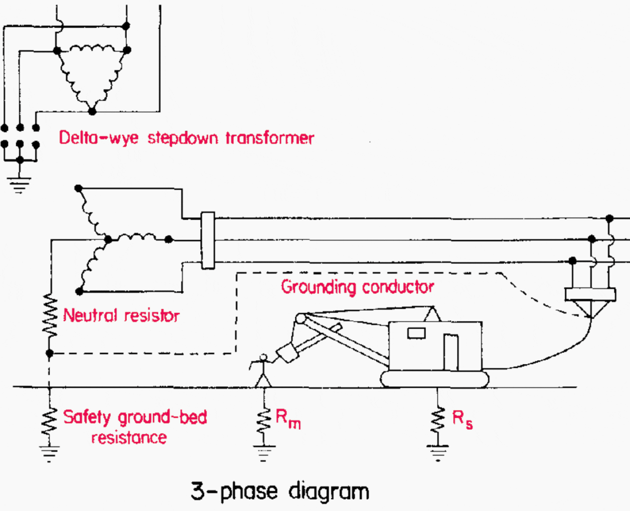
Figure 1: Three-phase diagram of an electrical shock hazard
Second, the energy available at the fault location should be limited by the grounding system. Arcing or sparking can ignite combustible material nearby. The air itself can become ionized, allowing it to carry massive amounts of current. Breakers, switchgear, and phase conductors can all be vaporized by a high-energy fault, and protective enclosures can be blown apart with explosive force.
Controlling the maximum allowable fault current significantly reduces the risk of fire and minimizes equipment damage.
Third, overvoltage control is critical. An overvoltage condition can occur as a result of equipment coming into contact with a higher voltage system, or as a result of transient phenomena such as lightning strikes, intermittent ground faults, autotransformer connections, or switching surges.

Figure 2 depicts an electrical shock hazard: a circuit for a line-to-ground fault.
In these cases, the maximum ratings for cable insulation, transformer windings, relay contractors, and so on may be temporarily exceeded. This does not usually result in immediate equipment failure, but component parts of the electrical system are gradually overstressed and weakened as a result of repeated exposure.
This results in premature failures decreased component life and mysterious “nuisance trips” that occur for no apparent reason. Most sources of transient overvoltages can be reduced or eliminated by providing a path between the transformer neutral and the ground.
If the relative tripping levels and speeds are not properly established, nearby breakers may fail to trip when they should, and a minor problem may turn into a major disaster. As a result of poor relay coordination, power to half a mine may go out, and much time may be lost in the effort to trace and locate the trouble spot.
As a result, the relaying system must be configured so that sufficient fault current can flow even at the lowest level of the power distribution chain to allow the protective circuitry to detect it and take corrective action.
Suggested Reading – Engineers are concerned about the mystery of nuisance tripping incidents in transformer protection.
- Earthing systems
Several different grounding philosophies have held sway in the electrical industry over the last few decades, each with its own set of advantages and disadvantages. These grounding methods are discussed further below.
Reactance-grounded systems are not discussed in the following sections because they are not commonly used in industrial power systems.
2.1 Neutral Ungrounded
Because of its simplicity, the ungrounded system was most likely the first to be used. In this case, there are no intentional ground connections in the system. A perfect ungrounded system, however, cannot exist because any current-carrying conductor can be coupled to ground via a variety of paths, including the distributed capacitance of its wiring or motor windings.

Figure 3: Capacitance coupling in an unconnected system.
Because there is no way for the fault current to find a complete circuit back to the source, the first line-to-ground fault on such a system will have very little effect, and its magnitude will be very small or nil. Because of the low fault current, there is no flash hazard and no equipment damage.
The circuit continues to operate normally with no interruption of power, which is an important consideration in industries where downtime is critical. Because its effects are insignificant, the first fault is frequently difficult to locate.
Frequently, no repair effort is made until a second fault occurs, bringing with it the risks of arcing, heavy current flow, and equipment damage. Because the entire system is “floating,” transient overvoltages are uncontrollable. Except for the issue of accidental contact with a higher voltage system, all of the previously mentioned overvoltage sources are boosted by distributed capacitance to the ground.
Additional research – Ground faults in ungrounded systems (risks & detection)
2.2 Neutral with a Firm Foundation
The solidly grounded neutral is another option. The first ground fault causes a significant neutral current flow, which is quickly detected by protective circuitry and shuts down the bad section.
Overvoltages are controlled because the system’s neutral is now solidly referenced to ground, as shown in Figure 4. The magnitude of the fault current causes hazards in this system. Detection equipment must be sensitive enough to detect low-level fault currents while also being fast enough to disconnect bad circuits before large faults disrupt system integrity.
Large fault currents, typically several thousand amperes, can explode protective enclosures, destroy equipment, and start fires, making this technique unsuitable for use in explosive atmospheres.

Figure 4: A well-grounded system
2.3 Grounded Low-Resistance Neutral
Inserting a resistor between the system neutral and the ground creates a low-resistance grounded-neutral system. Because of the resistance, ground-fault currents are limited to 50 to 600 A, but are typically around 400 A.
The ground connection controls transients, and enough fault current is available to activate protective relays. Although the flash hazard is not as severe as in a solidly grounded neutral system, a current flow of 400 A can still cause significant damage. The least sensitive ground relay should respond to 10% of the maximum ground-fault current to limit damage.

Figure 5: Resistance-based system
2.4 Grounded High-Resistance Neutral
The high-resistance grounded system, also known as the safety ground system, is perhaps the best technique and is required by law in coal-mining applications on portable or mobile equipment. The neutral grounding resistor is sized to limit ground-fault current to 50 A or less, depending on the system voltage level.
When the line-to-neutral potential is 1,000V or less, the grounding resistor must limit fault current to 25 A or less; when the voltage drop in the grounding circuit external to the resistor is greater than 1,000V, the voltage drop in the grounding circuit external to the resistor must be 100V or less under fault conditions. Sensitive relaying must detect faults on the order of a few amperes in this system to provide fault isolation and facilitate the quick location of the trouble spot. The fault current level is also low enough to virtually eliminate arcing and flashover hazards.
In addition, the ground connection serves to limit the amplitude of overvoltages. Loads, on the other hand, cannot be connected line to neutral because the grounding conductor must not carry any load current.
Further Reading – Underground distribution system transformers and equipment
- electrocution
Voltage and current levels that are harmful to humans must be determined in order to design an efficient and cost-effective safe grounding system. Distribution voltage and current levels have increased proportionally to the trend towards larger and more powerful mining machinery.
If electrocution is to be avoided, constant vigilance is required when using electricity. Even if a shock is not lethal, the involuntary movement caused by it can result in serious injury or death.
This demonstrates that the human “internal power supply” operates at approximately 50 Hz, which is precisely the frequency of the electric power generated in Europe. and is only 10 hertz away from the 60-hertz power generation frequency in the United States. This is an unfortunate coincidence, because tests have revealed that the most dangerous frequencies to which a person can be exposed are power frequencies ranging from 50 to 60 Hz.
Further reading – The 11 Deadliest Mistakes Made in a Power Substation by Young and Ignorant Electrical Engineers
- Mine grounding system characteristics
Since the introduction of electricity into coal mines, the concept of protecting mine electrical equipment and personnel from the consequences of ground faults has existed. A suitable grounding system has always been a difficult problem for the coal mining industry, more complex and difficult than in other industries.
4.1 Ground Mattresses
In addition to the phase conductors, electrical distribution cables and overhead transmission circuits carry one or more grounding conductors into the mine for mine use. Each piece of AC equipment has its frame solidly connected to a safety ground bed consisting of buried horizontal conductors or driven rods, or a combination of the two, via these grounding conductors.
As shown in Figure 6, the neutral of the substation transformer secondary is also connected to the safety ground bed via the neutral grounding resistor.

Figure 6: Substation simplified single-line diagram
It should be noted that many important components are missing from this diagram for the sake of simplicity.
The substation actually requires two ground beds that are kept apart. Lightning discharges and other primary surging conditions in transformers are directed to the system or station ground. The system and safety grounds must be kept separate so that current flow from one does not enter the other.
A person walking through the area underlain by the grid could bridge a lethal potential gradient with his or her feet, depending on the physical extent of the grid. Metallic objects within the potential gradient field can also be elevated to dangerous potentials, rendering them lethal to touch.
Figures 7 and 8 depict typical step and touch potentials.

Step potentials near a grounded structure (Figure 7)
These potential step and touch hazards apply to both the system and the safety ground beds. The dangers of a high-resistance safety ground bed, however, are found at the mining equipment rather than near the bed.
Figure 8: Potentials for touch near a grounded structure
The most pernicious aspect of the safety ground system is that the equipment connected to it is kept at safety ground-bed potential rather than earth potential. Any safety ground-bed current flow can render every piece of mine equipment potentially lethal unless the bed has low resistance.
Faults to earth, coupling from lightning strikes to system ground, lightning strikes to safety grounded machinery, and stray currents from DC haulage systems can all cause the flow.
Figures 9, 10, and 11 depict three such examples. As a result, elevated frame potential is a problem not only on the machine where it occurs, but everywhere with high-resistance ground beds.
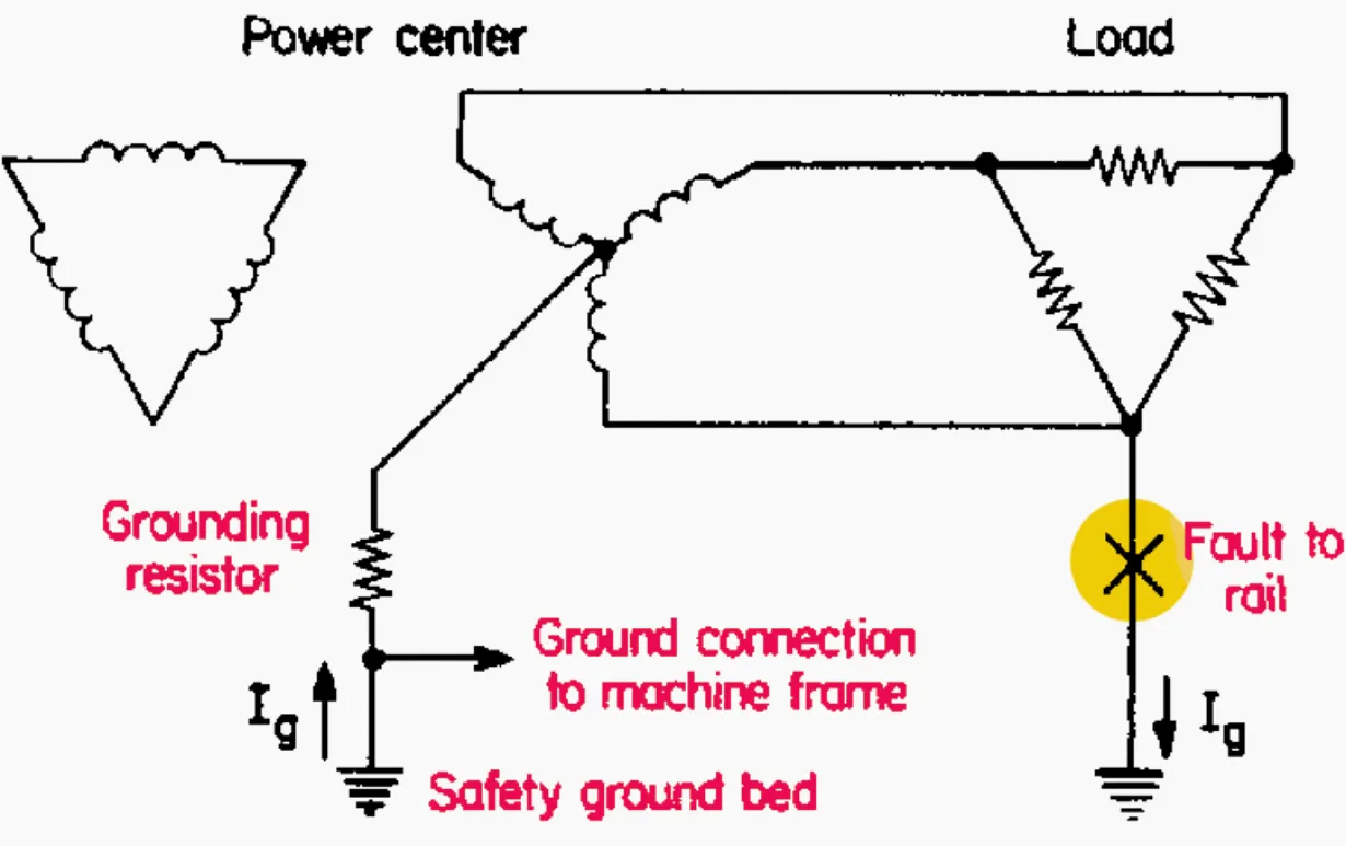
Figure 9 -A line-to-earth fault causes current to flow through the safety ground.

Figure 10: Lightning strikes equipment, causing current to flow through the safety ground bed.

Figure 11: Lightning strike current flowing through the system ground bed, raising the safety ground bed.
4.2 Underground Mining Grounding
In the early days of underground coal mining, a metal rod was driven into the mine floor and used as ground. This arrangement proved to be completely unacceptable in almost every case, with test measurements indicating 25 or more resistance. Mining machinery’s contact resistance with the mine floor, with the exception of pumps, proved to be too high for adequate grounding.
Rail haulage track systems, despite being frequently poorly bonded, demonstrated significantly lower ground resistance than most metallic rods driven specifically for that purpose.
Figure 12 depicts a simplified form of the bipower (mixed AC-DC) system used in underground coal mines.
Figure 12: Simplified mine power system single-line diagram
Three-phase alternating current power enters the mine after transformation to power the various three-phase alternating current loads. Some of the alternating current power is converted to direct current (DC) at rectifier stations to power the locomotive system and, on occasion, DC face equipment. Any DC face machinery is frequently powered by rectifiers located in the mine section.
With the exception of the tram system, all DC and AC equipment frames are linked to a common junction that is connected to the surface safety ground bed. Grounding conductors must be continuous and this continuity must be verified for the system to be effective. This is ensured by ground-check monitors.
Trolley locomotives typically use the overhead trolley wires as a positive conductor and the tracks as a negative conductor. Neither of these is connected to the frame ground of the rectifier station. However, because the track is in contact with the mine floor, the tram system’s negative conductor is grounded.
Despite the presence of all of these grounding points, the AC grounding system must be isolated from separate DC power systems. If not, DC may appear in the AC grounding system, raising it above true ground potential. If there is an AC ground current, it will be offset by the DC level.
The main concern is with tram installations, which achieve isolation by having no common points between the AC and DC systems. Various techniques for maintaining separation or eliminating DC offsets while grounding DC face equipment frames have been tried.
Power Engineering Course: Relay Control and Protection For LV/MV/HV Switchgear is a recommended course.
4.3 Grounding of Face Equipment
Because of the voltage drop in the track, the ground potentials of the DC and AC equipment frames are not necessarily equal when a working section employs an AC continuous miner powered by a section power centre and DC shuttle cars powered by the tram system.
This issue could be solved by disconnecting the low-voltage AC neutral point from the power-center frame as well as the high-voltage grounding system and connecting it to the track via an insulated cable, as shown in Figure 13.
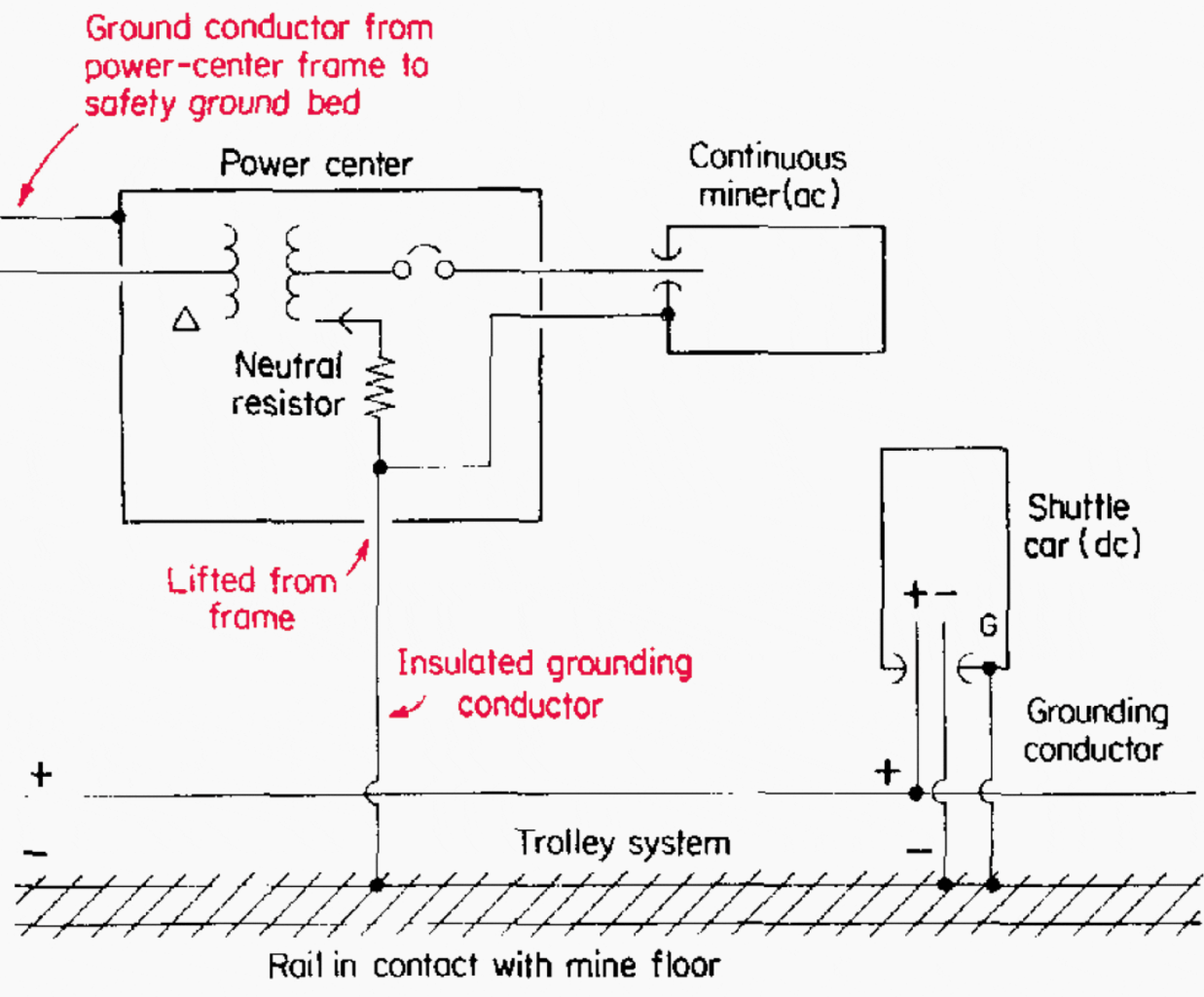
Figure 13: A mixed AC/DC mine power system with a DC load powered by the tram system.
The AC face-equipment frames are still connected to the low-voltage neutral point. This technique should equalise the low-voltage AC and DC equipment frame potentials, eliminating DC offset issues. This method is not without difficulties. If any track rail bonds between the AC and DC low-voltage ground points are faulty, the DC frame potentials may be elevated in comparison to the AC frames.
Furthermore, the power centre must always be kept a safe distance from the tracks in order to maintain isolation between the track and high-voltage grounding systems.
Suggested reading – Handbook for the use of neutral earthing resistors (NERs) in substations.
4.4 Track Contact
The rectifier frame is grounded by the AC system, as previously mentioned for trolley systems, but the negative conductor is grounded to the mine floor via the track. There is no internal connection between the rectifier output (or the trolley distribution system) and its frame in order to maintain isolation.
If the rectifier is on the mine floor, there may be a common point from the track (DC) to the rectifier frame (AC). The common point through the earth should ideally have a much higher resistance than the rail itself so that all rectifier current returns in the rail.
Although less common, leakage of the trolley-wire insulator to the roof or rib can have the same effect. When the sum of the mine floor resistance and equipment frame contact resistances is too low, DC current flow is permitted through the earth, resulting in DC offset currents on any mining machine and electrical system.

Figure 14 shows a mine rail track.
Rectifiers should be placed no closer than 25 feet from the track to help minimize problems. The rectifier frame can be insulated from the mine floor in extreme cases.
As previously stated, haulage conversion units are the primary source of DC offset currents. Stray DC currents, regardless of their source, can exist on all AC grounds within the mine. This problem is exacerbated by the fact that these currents can travel through water pipes and hoses, as well as through anything conductive.
A current flow is possible while they are touching, but arcing may occur when they separate.
Recommended reading: Practical troubleshooting of a power outage in a fully operational 33/11 kV substation
4.5 Surface Mine Grounding
A surface coal mine’s grounding system is similar to that of an underground mine. To convert the incoming utility voltage to the lower potential required by the mining machines, one or more substations with resistance-grounded secondaries are used. Pit distribution is carried on overhead lines or cables at this level to supply switch houses located near the specific piece of equipment.
The power circuit from the switch house to the machine is completed by a trailing cable. A switch house may be linked by cable to a portable substation, which provides lower voltage power to production, auxiliary, or lighting equipment.
Substation grounding consists of a system and a safety ground bed that are physically separated and electrically isolated from one another. Grounding conductors run from the safety ground bed to every piece of equipment. The neutrals of the portable substation transformer secondary are resistance grounded to the equipment frame.
Pit mine substation and switch house (Figure 15) (photo credit: meglab.ca)
Unlike underground coal mines, where the entire secondary distribution system is underground, both the primary and secondary lines in a surface mine are exposed to lightning. In fact, direct strokes are used on equipment such as draglines and shovels (see Figure 10).
To provide the best lightning protection, the grounding system must have the lowest possible surge impedance. The key here is to provide numerous short, direct paths to Earth.